Datasheet
Overview
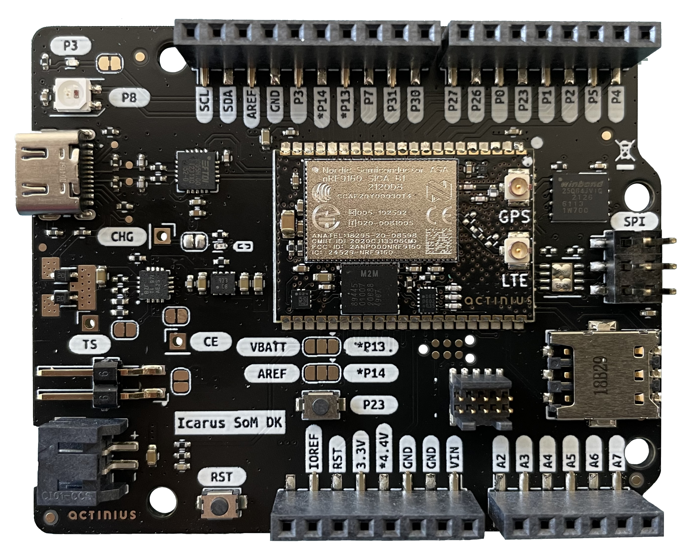
The Icarus SoM DK is a single board development kit for evaluation and development on the Icarus SoM. The Icarus SoM DK features the nRF9160 SiP from Nordic Semiconductor which provides low-power LTE-M and NB-IoT connectivity, GPS, a low-power 3-axis accelerometer and an on-board eSIM. The development kit provides interfacing to the SoM through USB-C, a set of user LEDs, a reset and user button, battery charging, power management, and a external nano SIM connector. The board is also Arduino Uno Rev3 compatible which makes using external shields possible.
Features
- Icarus System on Module
- Application processor:
- ARM® Cortex M33 with 1 MB Flash and 256 kB RAM
- ARM® Trustzone®, ARM® Cryptocell 310
- Connectivity:
- LTE Cat-M1, LTE CAT-NB1 (NB-IoT) with Global Coverage
- SSL / TLS & Secure FOTA support
- PSM and eDRX support
- On-board eSIM & SIM switching circuit for external SIM
- GPS (L1 C/A)
- Sensors, devices, and buttons:
- LIS2DH12 3-axis low-power accelerometer
- 64 Mbit SPI NOR flash
- WS2812 / NeoPixel addressable RGB LED
- Blue user LED
- General Purpose button
- Reset button
- FTDI USB to serial converter
- Power:
- Battery voltage measurement circuit
- Current measurement connector connected directly to the battery
- LiPo Charger with MPPT
- Under-voltage and over-voltage protection
- USB-C connector
- VIN pin for powering directly from a battery or to separately power the radio.
- Peripherals:
- I2C / UART / SPI / I2S with EasyDMA
- up to 22 GPIO
- up to 8 12-bit, 200ksps ADC with EasyDMA
- up to 4 PWM Units
- SWD 10-pin JTAG programming connector
- SWD 6-pin TagConnect programming connector
- Compatible with the Arduino Uno Rev3
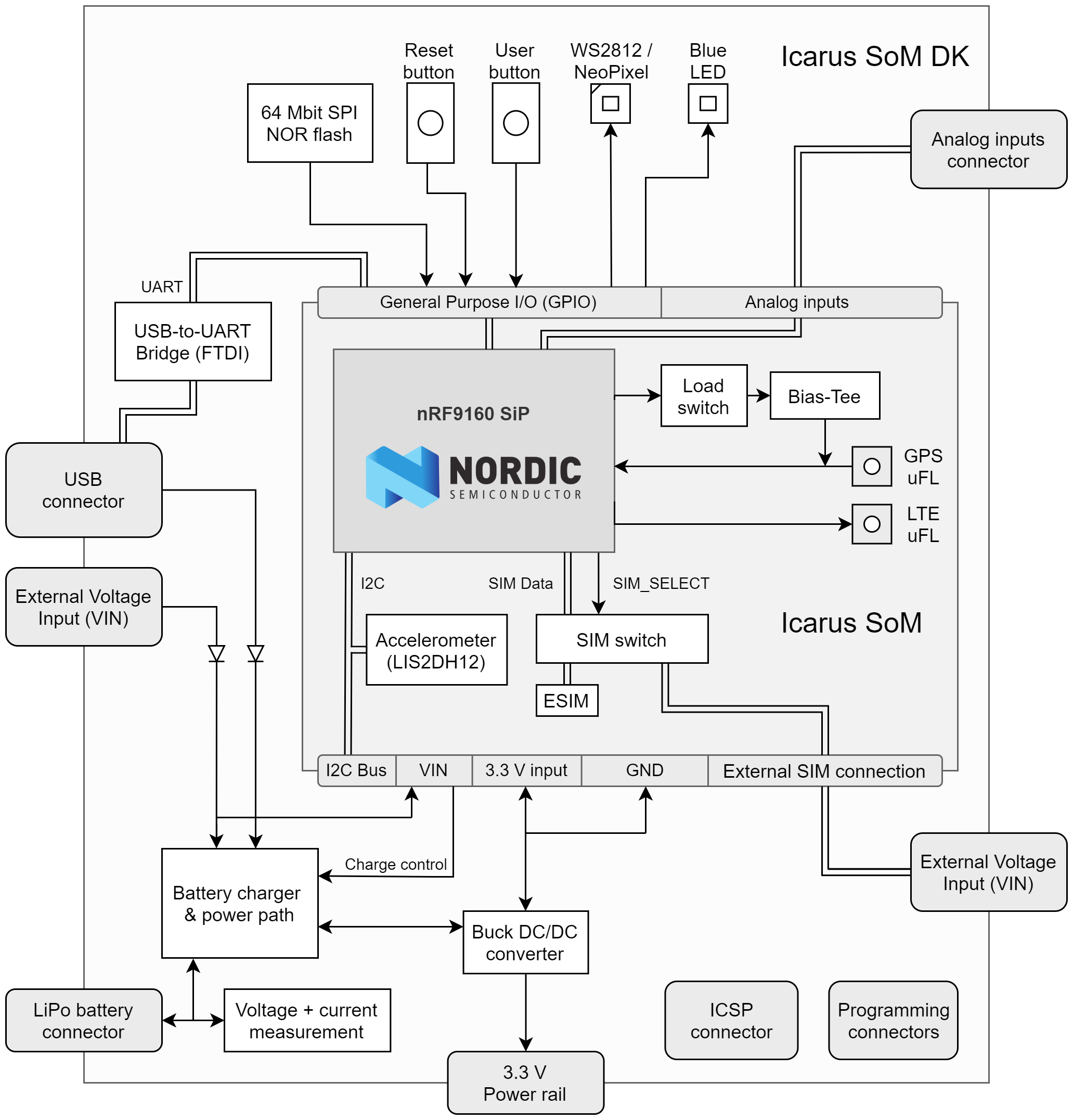
Block Diagram
Pin description
External pins available to user
| # | Label | Description | Device-tree node |
|---|---|---|---|
| 1 | NC | Not Connected | - |
| 2 | IOREF | I/O reference, connected to 3.3V | - |
| 3 | RST | Reset of the nRF9160 | - |
| 4 | 3.3V | 3.3V Power output | - |
| 5 | 4.4V | Power output between Vbat and 4.4V | - |
| 6 | GND | Ground pin | - |
| 7 | GND | Ground pin | - |
| 8 | VIN | Power input pin (4.35V to 10.5V) | - |
| 9 | A2 | AIN2 / nRF9160 P0.15 | gpio0 |
| 10 | A3 | AIN3 / nRF9160 P0.16 | gpio0 |
| 11 | A4 | AIN4 / nRF9160 P0.17 | gpio0 |
| 12 | A5 | AIN5 / nRF9160 P0.18 | gpio0 |
| 13 | A6 | AIN6 / nRF9160 P0.19 | gpio0 |
| 14 | A7 | AIN7 / nRF9160 P0.20 | gpio0 |
| 15 | P4 | nRF9160 P0.04 | gpio0 |
| 16 | P5 | nRF9160 P0.05 | gpio0 |
| 17 | P2 | nRF9160 P0.02 | gpio0 |
| 18 | P1 | nRF9160 P0.01 | gpio0 |
| 19 | P23 | nRF9160 P0.23 | gpio0 |
| 20 | P0 | nRF9160 P0.00 | gpio0 |
| 21 | P26 | nRF9160 P0.26 | gpio0 |
| 22 | P27 | nRF9160 P0.27 | gpio0 |
| 23 | P30 | nRF9160 P0.30 | gpio0 |
| 24 | P31 | nRF9160 P0.31 | gpio0 |
| 25 | P7 | nRF9160 P0.07 | gpio0 |
| 26 | P13 | nRF9160 P0.13 or NC (Jumper-dependent) | gpio0 |
| 27 | P14 | nRF9160 P0.14 or NC (Jumper-dependent) | gpio0 |
| 28 | P3 | nRF9160 P0.03 | gpio0 |
| 29 | GND | Ground pin | - |
| 30 | AREF | NC or AIN1 (Jumper-dependent) | gpio0 |
| 31 | SDA | I2C SDA pin | i2c2 |
| 32 | SCL | I2C SCL pin | i2c2 |
| - | TS | Pin for optional battery thermistor | - |
| - | CHG | Pin for battery charging indication | - |
| - | CE | Pin for enabling/disabling charging | - |
nRF9160 pins connected on the Icarus SoM DK internally
| nRF9160 pin | Function | Device-tree node |
|---|---|---|
| P0.03 | Blue LED | led0 / pwm-led0 |
| P0.08 | NeoPixel RGB LED | spi1 |
| P0.12 | SIM select pin | gpio0 |
| P0.23 | Connected to the user button | gpio0 / button0 |
| P0.24 | SPI NOR Flash chip select | gpio0 / spi3 |
| P0.28 | Accelerometer Interrupt 2 | lis2dh12-accel |
| P0.29 | Accelerometer Interrupt 1 | lis2dh12-accel |
The connections described in the table above are reserved for the specified functionality and should not be used for other functionalities. Using them can cause some devices on the Icarus SoM DK to stop working correctly.
Recommended Operating Conditions
| Parameter | MIN | TYP | MAX | UNITS |
|---|---|---|---|---|
| Operating Temperature | -20 | 25 | 85 | °C |
| Battery Voltage | 3.2 | 3.7 | 4.2 | V |
| V_USB Voltage | 4.35 | 5 | 10.2 | V |
| V_IN Voltage | 4.35 | 10.2 | V |
Absolute Maximum Ratings
| Parameter | MAX | UNITS |
|---|---|---|
| Input Voltage (V_USB or V_IN) | 28 | V |
Dimensions
| Parameter | VALUE | UNITS |
|---|---|---|
| Height | 55.2 | mm |
| 2.17 | in. | |
| Width | 68.57 | mm |
| 2.7 | in. |
Peripherals
The Icarus SoM DK hosts several peripherals that are connected to the nRF9160 internally or on the board. Descriptions of the peripherals and devices can be found below.
SPI NOR Flash
The Icarus SoM DK board provides the W25Q64JV with 64 MBit of SPI NOR flash, supported by Zephyr. This allows for storage of larger amounts of data. It also allows to store firmware update images on the flash which are received Over-The-Air (OTA).
The SPI NOR flash hardware connection has been described in the Icarus SoM DK device-tree under the arduino_spi / spi3 node. It has been defined as device w25q64jv@0 with label W25Q64. The flash can be selected using its Chip Select (CS) which is connected on P0.24 of the nRF9160. The SPI NOR flash can be tested using the JEDEC SPI-NOR Sample from Zephyr.
Accelerometer
The accelerometer on the board is the LIS2DH12 from ST. This ultra-low-power 3-axis accelerometer is connected to the nRF9160 through I2C (address 0x19) and features two interrupt pins, INT1 and INT2, which are connected to pins P0.28 and P0.29. The interrupt pins can be configured for multiple purposes including free-fall and motion detection (more info on this in the LIS2DH12 datasheet).
The accelerometer hardware connection has been described in the Icarus SoM DK device-tree under the arduino_i2c / i2c2 node. It has been defined as device lis2dh12-accel@19 with label LIS2DH12-ACCEL. For an example on how to read data from the accelerometer, see the Accelerometer sample.
Neopixel LED
The DK provides the WS2812 NeoPixel addressable RGB LED. Each of the 3 primary colors can achieve 256 levels of brightness, allowing for 16777216 full color display. It is connected to the nRF9160 through SPI.
The Neopixel LED hardware connection has been described in the Icarus SoM DK device-tree under the spi1 node. It has been defined as device ws2812@0 with label NEOPIXEL_LED. For an example on how to use the Neopixel LED, see the Neopixel and button sample
GPS
The GPS receiver on the Icarus SoM DK is embedded into the modem of the nRF9160. To successfully get a GPS fix, and receive location data, an active external GPS antenna must be connected (with a u.fl connector). An example of an antenna that can be used is the GNSS active patch antenna from Molex.
Configuring the voltage supply for the GPS antenna:
During operation, the modem inside the nRF9160 will automatically enable/disable the voltage supply for the GPS antenna when the GPS is active. It is doing this through the MAGPIO0 pin. During bootup, it is necessary to configure the modem through an AT command to use the MAGPIO pin. AT commands can be written to the nRF9160 modem using the at_cmd_write() function. This is an example of configuring the MAGPIO0 pin for GPS operation (notice how a specific frequency range for GPS is configured):
at_cmd_write("AT%XMAGPIO=1,0,0,1,1,1547,1577", NULL, 0, NULL);
Initialization and enabling of the GPS takes a few more steps. See the GPS sample and/or Nordic's nRF Connect SDK documentation for more information on initialization and reading GPS data using the Icarus.
eSIM and external SIM connection
SIM select configuration for nRF SDK v2.0.0 and up:
The SIM on the Icarus SoM must be selected through the device-tree if you are using nRF SDK v2.0.0 and up. Selecting the SIM is done using a device-tree overlay file in your project. Follow these steps to select the SIM through the device-tree:
- Create a new directory in your project folder named
boards:
$ cd <your-project-directory>
$ mkdir boards
$ cd boards
- Create an overlay file with the exact name of the board:
# When building for a non-secure application
$ touch actinius_icarus_som_dk_ns.overlay
- Add the following device-tree node to your overlay file:
&sim_select {
    sim = "external";
};
By changing the value of sim to "external" you select the external SIM. By changing the value of sim to "esim" you select the on-board eSIM. And what's left to do is to re-build your project (use a pristine build).
If the pin is left uninitialized, the modem will use the on-board eSIM.
Only change the SIM Select pin before enabling the modem. E.g. before writing the "AT+CFUN=1" AT command.
The Icarus SoM DK also provides the BOARD_SELECT_SIM_EXTERNAL configuration option to automatically select the external SIM on the SIM connector instead of the eSIM. This option can be enabled through the prj.conf of an application project.
Power
Power output:
The Icarus SoM DK uses a power management device in combination with a DC/DC converter to supply the board with power. The board can be powered using a LiPo battery, USB, or the VIN pin. The DC/DC converter can output a maximum current of 400 mA and provide a stable 3.3 V voltage rail.
Power supply limits:
As mentioned in the mechanical and electrical specifications, the maximum external input voltage (VIN) can be 10.2 V. The over-voltage protection of the Icarus SoM DK will be triggered at a external input voltage higher than 10.2 V. Inputs up to 28 V are permitted, however voltages over this limit can damage the board. The USB-port is also protected from voltage spikes.
Charger
Charging output:
The charger is able to charge a LiPo battery using the USB-port or any other power source connected to the VIN pin (e.g. a solar cell). The charger can provide 445 mA of fast charge current. The power management device on the DK also ensures that the USB and/or other VIN power source is not overloaded with charging.
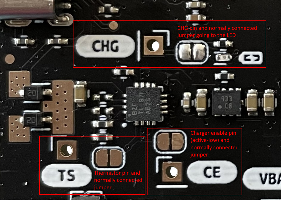
Charging LED:
Battery charging is indicated by a yellow charging LED on the DK. The board provides a jumper which can be used to disconnect the LED and save power. Simply cut the trace in between the jumper to disconnect the LED. The pin that indicates that the battery is charging is also exposed and labeled with CHG on the board. The CHG pin can be connected to one of the pins of the nRF9160 to check whether the battery is charging.
Enable/disable charger:
The DK provides a jumper and pin labeled CE that can be used to enable/disable the charger. The Charger Enable (CE) pin is normally connected to ground to enable charging (active-low). Cutting the trace in between the jumper and connecting the CE pin to 3.3 V will disable the charging circuit. This means that the battery can still be used to power the board, it will just not be charged anymore.
Connecting a battery thermistor:
The charging circuitry on the Icarus SoM DK provides a TS pin which can be used to connect a 10kΩ NTC thermistor for reading the battery temperature. The TS pin is normally grounded through a 10kΩ pull-down resistor. This resistor should be disconnected by cutting the trace of the jumper that is next to the TS pin.
Battery voltage measurement
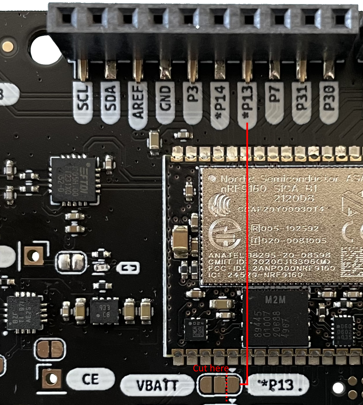
The Icarus SoM DK provides the user with the ability to read the battery voltage level through one of the nRF9160 ADC pins. The battery voltage is measured through a voltage divider which can be seen in the image below. This circuit connects VBAT to the AIN0 pin of the nRF9160 (P0.13):

Before reading the battery voltage level on the nRF9160, the voltage divider circuit must be connected. On the DK board, there is a jumper labeled with VBATT and P13. The jumper is normally connected to the P13 side (right) and goes to the external connector on the right. If the jumper is cut, it can be soldered to the VBATT side (left) which connects P0.13 / AIN0 to the battery voltage measurement circuit (See the image below for more clearification). This renders the external pin unusable.
Battery voltage measurement example:
See the ADC battery voltage measurement sample for more information of how to use the ADC as well as the conversion for the voltage divider.
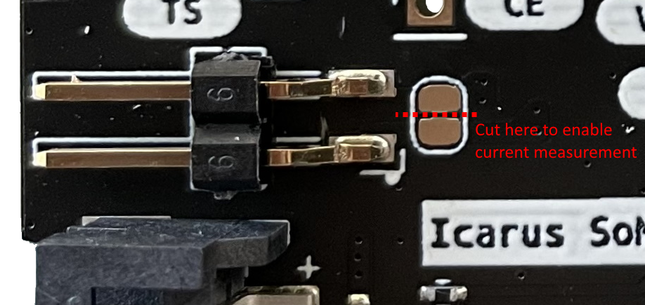
SoM current consumption measurement
The DK provides a way to measure the current consumption of the Icarus SoM by using the 2-pin header next to the battery connector. The pins can be connected to a multimeter or e.g. an OTII measurement device. The use of the 2-pin header to measure current requires you to cut the jumper next to it. When done measuring the current consumption, this jumper should be resoldered to ensure that the SoM gets powered.