Datasheet
Overview
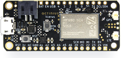
The Icarus is a cost-effective board combining the latest cellular IoT technologies on the market. It is equipped with the nRF9160 SiP which hosts an ARM® Cortex M33 processor, used for user applications. The SiP also contains a second processor that is dedicated to cellular communication (LTE-M / NB-IoT) and GPS.
The nRF9160 modem supports Power Saving Mode (PSM) to extend battery life and minimize power consumption. In PSM mode the Icarus sets a sleep timer, tells the network it will not be reachable during sleep. It will not be able to communicate until it wakes up again, but it can wake up at any time if it wants to connect and send data. The modem also supports extended discontinuous reception (eDRX). This allows the user to configure predefined intervals on which the board should wake up to listen for network messages. PSM and/or eDRX can be used together to prolong battery life and minimize power consumption.1
User applications are usually run on Zephyr RTOS. This is a scalable real-time operating system (RTOS) for embedded devices that have constrained resources. The OS borrows elements from Linux and may be familiar to Linux developers: e.g. kernel configuration using Kconfig and usage of the device-tree. Nordic Semiconductor has created its own fork of Zephyr which can be found here.
Features
- Application processor:
- ARM® Cortex M33 with 1 MB Flash and 256 kB RAM
- ARM® Trustzone®, ARM® Cryptocell 310
- Connectivity:
- LTE Cat-M1, LTE CAT-NB1 (NB-IoT) with Global Coverage
- SSL / TLS & Secure FOTA support
- PSM and eDRX support
- On-board eSIM & nano SIM
- GPS (L1 C/A)
- Sensors, devices, and buttons:
- LIS2DH12 3-axis low-power accelerometer
- 64 Mbit SPI NOR Flash
- RGB LED
- General Purpose button
- Reset button
- Power:
- Battery voltage measurement circuit
- LiPo Charger with MPPT
- Under-voltage and Over-voltage protection
- Can be powered from multiple power sources
- Peripherals:
- USB / I2C / UART / SPI / I2S with EasyDMA
- up to 18 GPIO
- up to 6 12-bit, 200ksps ADC with EasyDMA
- up to 4 PWM Units
- SWD on 6-pin TagConnect
- Fully compatible with the Adafruit FeatherWing standard specs
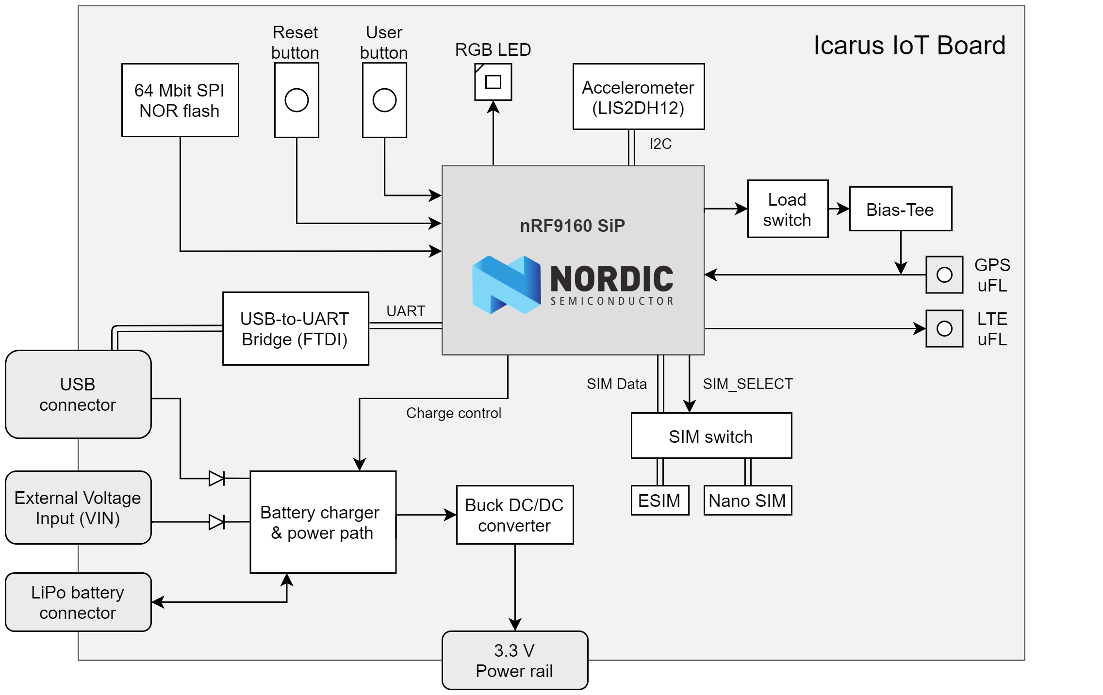
Block Diagram
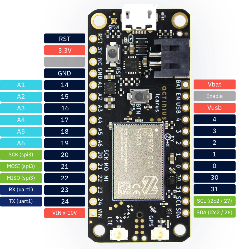
Pin description
External Pins available to user
| Icarus pin | Function | Description | Device-tree node |
|---|---|---|---|
| RST | Reset | Active low reset with internal pullup | - |
| 3.3V | Power output | Main 3.3 V supply | - |
| NC | - | Not connected | - |
| GND | Power output | Ground | - |
| 14 / A1 | GPIO / Analog in | nRF9160 P0.14 / AIN1 | gpio0 / adc_1 |
| 15 / A2 | GPIO / Analog in | nRF9160 P0.15 / AIN2 | gpio0 / adc_2 |
| 16 / A3 | GPIO / Analog in | nRF9160 P0.16 / AIN3 | gpio0 / adc_3 |
| 17 / A4 | GPIO / Analog in | nRF9160 P0.17 / AIN4 | gpio0 / adc_4 |
| 18 / A5 | GPIO / Analog in | nRF9160 P0.18 / AIN5 | gpio0 / adc_5 |
| 19 / A6 | GPIO / Analog in | nRF9160 P0.19 / AIN6 | gpio0 / adc_6 |
| 20 / SCK | GPIO / SPI pin | nRF9160 P0.20 / SPI SCK pin | gpio0 / spi3 |
| 21 / MOSI | GPIO / SPI pin | nRF9160 P0.21 / SPI MOSI pin | gpio0 / spi3 |
| 22 / MISO | GPIO / SPI pin | nRF9160 P0.22 / SPI MISO pin | gpio0 / spi3 |
| 23 / RX | GPIO / UART pin | nRF9160 P0.23 / UART RX pin | gpio0 / uart1 |
| 24 / TX | GPIO / UART pin | nRF9160 P0.24 / UART TX pin | gpio0 / uart1 |
| VIN | Power input | Voltage input (maximum 10.2 V) | - |
| VBAT | Power input | Battery voltage input | - |
| EN | Power enable | Power enable pin (pull low to disable power) | - |
| USB | Power input | USB voltage input | gpio0 |
| 4 | GPIO | nRF9160 P0.04 | gpio0 |
| 3 | GPIO | nRF9160 P0.03 | gpio0 |
| 2 | GPIO | nRF9160 P0.02 | gpio0 |
| 1 | GPIO | nRF9160 P0.01 | gpio0 |
| 0 | GPIO | nRF9160 P0.00 | gpio0 |
| 30 | GPIO | nRF9160 P0.30 | gpio0 |
| 31 | GPIO | nRF9160 P0.31 | gpio0 |
| SCL | GPIO / I2C pin | nRF9160 P0.26 / I2C SCL pin | gpio0 / i2c2 |
| SDA | GPIO / I2C pin | nRF9160 P0.27 / I2C SDA pin | gpio0 / i2c2 |
nRF9160 pins connected on Icarus internally
| nRF9160 pin | Function | Device-tree node |
|---|---|---|
| P0.05 | User button | button0 |
| P0.10 | Red LED | led0 / pwm-led0 |
| P0.11 | Green LED | led1 / pwm-led1 |
| P0.12 | Blue LED | led2 / pwm-led2 |
| P0.28 | Accelerometer Interrupt 1 | lis2dh12-accel |
| P0.29 | Accelerometer Interrupt 2 | lis2dh12-accel |
| P0.08 | SIM select pin | gpio0 |
| P0.13 / AIN0 | Battery voltage measurement | adc_0 |
| P0.06 | USB - FTDI serial RX | uart0 |
| P0.09 | USB - FTDI serial TX | uart0 |
| P0.07 | USB - FTDI serial RTS | uart0 |
| Charger enable pin (Icarus v2.0) | gpio0 (Icarus v2.0) | |
| P0.25 | USB - FTDI serial CTS | uart0 |
| FLASH memory SPI CS pin (Icarus v2.0) | gpio0 (Icarus v2.0) |
The connections described in the table above connect several devices with the nRF9160 on the Icarus. They are not externally available to the user and are reserved for the specified functionality. These reserved nRF9160 pins should not be used for other functionalities. Using them can cause some devices on the Icarus to stop working correctly.
TagConnect Programming Pins
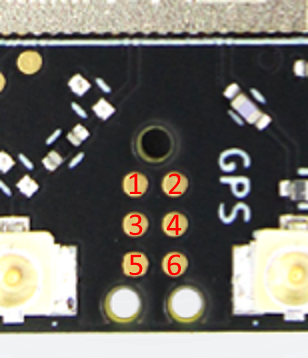
| TagConnect pin | nRF9160 pin | Description |
|---|---|---|
| 1 | 3.3 V | Power |
| 2 | SWDIO | SWDIO |
| 3 | nReset | Reset |
| 4 | SWDCLK | SWDCLK |
| 5 | GND | Ground |
| 6 | NC | Not connected |
The TagConnect pins on the Icarus are used to program the board through a J-Link programmer. Any compatible J-link programmer can be used, for example:
- Segger J-Link (EDU, EDU Mini, BASE, PLUS, etc...)
- nRF5340 development kit
- nRF9160 development kit
A TagConnect cable is necessary to connect to the pins. It is recommended to use the TC2030-CTX-NL cable.
Mechanical and electrical specifications
Recommended Operating Conditions
| Parameter | MIN | TYP | MAX | UNITS |
|---|---|---|---|---|
| Operating Temperature | -20 | 25 | 85 | °C |
| Battery Voltage | 3.2 | 3.7 | 4.2 | V |
| V_USB Voltage | 4.35 | 5 | 10.2 | V |
| V_IN Voltage | 4.35 | 10.2 | V |
Absolute Maximum Ratings
| Parameter | MAX | UNITS |
|---|---|---|
| Input Voltage (V_USB or V_IN) | 28 | V |
Dimensions
| Parameter | VALUE | UNITS |
|---|---|---|
| Height | 22.85 | mm |
| 0.9 | in. | |
| Width | 50.8 | mm |
| 2 | in. |
Devices
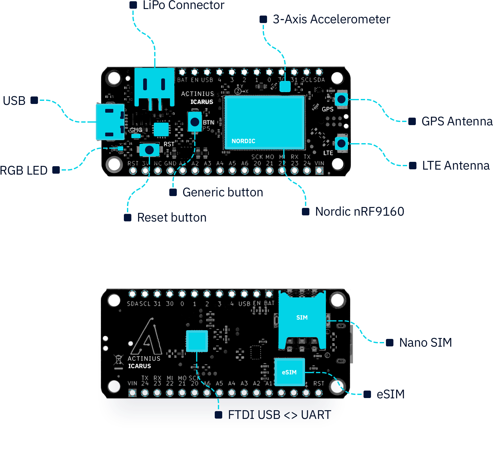
The Icarus hosts several connectors and devices that are connected to the nRF9160 through internal connections. The pins used for the connections are reserved and should not be used for other purposes (as already described in the Icarus pin description). A diagram of the devices is shown in the image below.
SPI NOR Flash
Since version 2.0 of the Icarus, the board provides the W25Q64JV 64 MBit SPI NOR flash which is supported by Zephyr. This allows for storage of larger amounts of data. It also allows to store firmware update images on the flash which are received Over-The-Air (OTA).
The SPI NOR flash hardware connection has been described in the Icarus device-tree under the spi3 node. It has been defined as device w25q64jv@0 with label W25Q64. The SPI NOR flash can be tested using the JEDEC SPI-NOR Sample from Zephyr.
Accelerometer
The accelerometer on the board is the LIS2DH12 from ST. This ultra-low-power 3-axis accelerometer is connected to the nRF9160 through I2C (address 0x19) and features two interrupt pins, INT1 and INT2, which are connected to pins P0.28 and P0.29. The interrupt pins can be configured for multiple purposes including free-fall and motion detection (more info on this in the LIS2DH12 datasheet).
The accelerometer hardware connection has been described in the Icarus device-tree under the i2c2 node. It has been defined as device lis2dh12-accel@19 with label LIS2DH12-ACCEL. For an example on how to read data from the accelerometer, see the Accelerometer sample.
GPS
The GPS receiver on the Icarus is embedded into the modem of the nRF9160. To successfully get a GPS fix, and receive location data, an active external GPS antenna must be connected (with a u.fl connector). An example of an antenna that can be used is the GNSS active patch antenna from Molex.
Configuring the voltage supply for the GPS antenna:
During operation, the modem inside the nRF9160 will automatically enable/disable the voltage supply for the GPS antenna when the GPS is active. It is doing this through the MAGPIO0 pin. During bootup, it is necessary to configure the modem through an AT command to use the MAGPIO pin. AT commands can be written to the nRF9160 modem using the at_cmd_write() function. This is an example of configuring the MAGPIO0 pin for GPS operation (notice how a specific frequency range for GPS is configured):
at_cmd_write("AT%XMAGPIO=1,0,0,1,1,1574,1577", NULL, 0, NULL);
Initialization and enabling of the GPS takes a few more steps. See the GPS sample in the nrf/samples folder and/or Nordic's nRF Connect SDK documentation for more information on initialization and reading GPS data using the Icarus.
eSIM and external SIM
SIM selection:
The Icarus provides the user with 2 options regarding SIM usage for LTE-M/NB-IoT communication. Either using the on-board eSIM or using an external nano-SIM. The SIM can be selected using the SIM select pin on P0.08:
| Selection pin (P0.08) | Selected SIM |
|---|---|
| HIGH (1) | on-board eSIM |
| LOW (0) | external nano-SIM |
If the pin is left uninitialized, the modem will use the on-board eSIM.
Only change the SIM Select pin before enabling the modem. E.g. before writing the "AT+CFUN=1" AT command.
SIM select configuration for nRF SDK v2.0.0 and up: The SIM on the Icarus must be selected through the device-tree if you are using nRF SDK v2.0.0 and up. Selecting the SIM is done using a device-tree overlay file in your project. Follow these steps to select the SIM through the device-tree:
- Create a new directory in your project folder named
boards:
$ cd <your-project-directory>
$ mkdir boards
$ cd boards
- Create an overlay file with the exact name of the board:
# When building for a non-secure application
$ touch actinius_icarus_ns.overlay
- Add the following device-tree node to your overlay file:
&sim_select {
    sim = "external";
};
By changing the value of sim to "external" you select the external SIM. By changing the value of sim to "esim" you select the on-board eSIM. And what's left to do is to re-build your project (use a pristine build).
SIM select configuration for nRF SDK v1.9.1 and down:
The external SIM on the Icarus can be selected using a configuration option if you are using nRF SDK v1.9.1 and down. You can set the following option: BOARD_SELECT_SIM_EXTERNAL=y in the prj.conf to automatically select the external SIM on the SIM connector. The on-board eSIM is used by default if the config option is not set.
Included eSIM dataplan: The on-board eSIM of the Icarus provides LTE-M (and in select service areas NB-IoT) data connectivity, wherever supported by our Telecom Agreements in the EU and US. The Icarus includes a free eSIM bundle with 10 MB of data for 3 months. A data plan can be purchased for the eSIM after the initial three months. The eSIM can be activated by registering your Icarus device on the Actinius IO platform.
Power
Power output: The Icarus uses a power management device in combination with a DC/DC converter to supply the board with power. The board can be powered using a LiPo battery, USB, or the VIN pin. The DC/DC converter can output a maximum current of 400 mA and provide a stable 3.3 V voltage rail.
Power supply limits: As mentioned in the mechanical and electrical specifications, the maximum external input voltage (VIN) can be 10.2 V. The over-voltage protection of the Icarus will be triggered at a external input voltage higher than 10.2 V. Inputs up to 28 V are permitted, however voltages over this limit can damage the board. The USB-port is also protected from voltage spikes.
Charger
Charging output: The charger is able to charge a LiPo battery using the USB-port or any other power source connected to the VIN pin (e.g. a solar cell). The charger can provide the following amount of fast charge current:
| Icarus version | Fast charge current |
|---|---|
| v1.4 | 600 mA |
| v2.0 | 445 mA |
The power management device on the Icarus also ensures that the USB and/or other VIN power source is not overloaded with charging.
Charging LED: Battery charging is indicated by a yellow charging LED on the Icarus (LED uses 13 mA). Version 2.0 of the Icarus includes a jumper on the bottom of the board which can be used to disconnect the LED and save power, for example when connected to a solar panel.
Enable/disable charger:
On Icarus v2.0 and up, there is a dedicated pin (P0.07) reserved to enable/disable the charger. The pin is connected to the charging circuit and disables output to the battery if put to HIGH. Operation using the battery or any other input will remain unaffected.
Setting the default charger configuration: When using Icarus v2.0 and nRF SDK v2.0.0 and up, it is possible to configure a default state for the charger through the device-tree. This must be done through a device-tree overlay file in your project. Follow these steps to set a default charger configuration:
- Create a new directory in your project folder named
boardsif it doesn't already exist:
$ cd <your-project-directory>
$ mkdir boards
$ cd boards
- Create an overlay file with the exact name of the board:
# When building for a non-secure application
$ touch actinius_icarus_ns.overlay
- Add the following device-tree node to your overlay file:
&charger_enable {
    charger = "auto";
};
Setting the value of charger to "auto" will enable the charger. Setting the value of charger to "disabled" will disable the charger. By default, if nothing is specified in the overlay file, the charger is enabled and set to auto.
During the secure part of your application the charger will always be enabled, e.g. when the board is running the SPM or MCUBoot. There is currently no option to disable the charger in these stages. The board will change to the configuration, specified in the device-tree overlay file, once it switches to the user application.
Battery voltage measurement
The Icarus provides the user with the ability to read the battery voltage level through one of the nRF9160 ADC pins. The battery voltage is measured through a voltage divider which can be seen in the image below. This circuit connects VBAT to the AIN0 pin of the nRF9160 (P0.13):
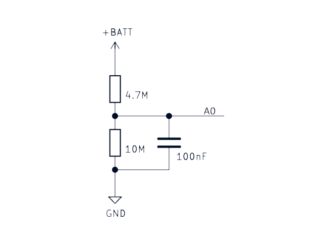
Battery voltage measurement example: See the ADC battery voltage measurement sample for more information of how to use the ADC as well as the conversion for the voltage divider.
CAD Symbols and Footprints
Symbols and footprints for the Icarus IoT Board are available for all popular CAD software on SnapEDA
- PSM and eDRX support depend on the combination of the network operator and the SIM that is used with the Icarus. Make sure to check whether your network operator and SIM support these features.↩