Introduction
RS232/RS485 and Level Translator FeatherWing
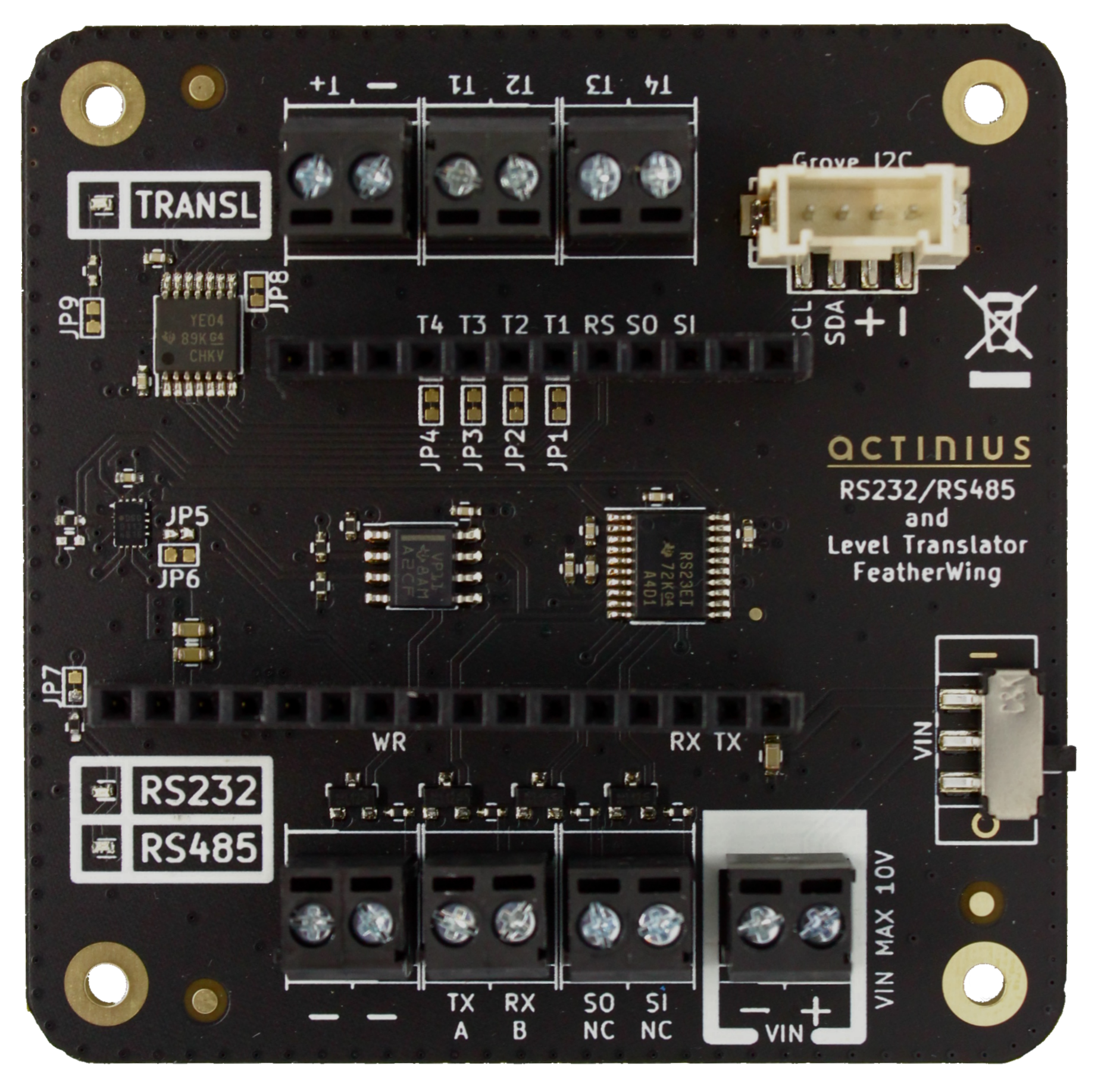
The RS232/RS485 and Level Translator FeatherWing incorporates the following:
- TXB0104PWR Bi-Directional Level Translator
- SN65HVD11D RS485 Driver
- TRS3223ECPWR RS232 Driver
- Grove Connector connected to the Feather Board's I2C
- LEDs indicating which parts are active (Level Translator/RS232/RS485)
- VIN Switch (only for compatible Feather Boards)
- (Screw) Terminal Blocks for all connections
- TVS Protection on the RS* IOs
Power
The board is powered via the 3V pin of the Feather Board, which means that the set of Feather board & RS232/RS485 FeatherWing can be powered via USB, VUSB pin, LiPo Battery etc.
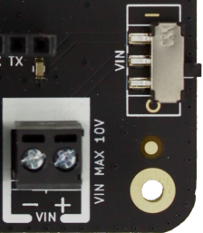
If you are using a Feather board that accepts VIN on its 16th pin, such as the Icarus IoT Dev Board, then you can feed power to the VIN Terminal Blocks up to the voltage level allowed by your Feather Board (The Icarus allows for up to 10V VIN input before the over-voltage protection kicks in). Since the FeatherWing format specs do not specify the 16th pin, the VIN connection may not be compatible with other Feather Boards. In that case, please leave the VIN Terminal Block unconnected and/or the VIN switch set to off to avoid any risk of damage.
Pinout
| Connection | Description |
|---|---|
| Grove Connector | Connected to the 3V rail (nominally 3.3 V) and the I2C of the Feather Board |
| Pin Headers | |
| T1, T2, T3, T4 | Port A of the Level Translator (Bi-Directional, 1.2 V - 3.6 V) |
| TX | (Low voltage side) TX output of the Feather Board, for use with RS232/RS485 |
| RX | (Low voltage side) RX input of the Feather Board, for use with RS232/RS485 |
| SO | (Low voltage side) Signal Out pin, for use with RS232. Can be used for signals such as DTR or as TX for a second UART |
| SI | (Low voltage side) Signal In pin, for use with RS232. Can be used for signals such as CTS or as RX for a second UART |
| (Screw) Terminal Blocks | |
| T1, T2, T3, T4 | Port B of the Level Translator (Bi-Directional, 1.65 V - 5.5 V) |
| TX/A | TX output pin (RS232) or A pin (RS485) |
| RX/B | RX in pin (RS232) or B pin (RS485) |
| SO | RS232 Signal Out pin |
| SI | RS232 Signal In pin |
| Control Signals | |
| RS | Selects between RS232 and RS485. Low: RS485, High: RS232 |
| WR | Selects between Read or Write mode on the RS485 driver. Low: Read, High: Write |
Please note that T1, T2, T3, T4 are not to be used for sustained ON/OFF states but only for driving "switching" communications such as UART/I2C/SPI etc.
Jumper Settings
| Jumper | Default State | Description |
|---|---|---|
| JP1 | Closed | Connects the A Port side of Level Translator pin T1 |
| JP2 | Closed | Connects the A Port side of Level Translator pin T2 |
| JP3 | Closed | Connects the A Port side of Level Translator pin T3 |
| JP4 | Closed | Connects the A Port side of Level Translator pin T4 |
| JP5 | Open | Sets the RS485 RX module to be always activated. This jumper should only be closed with JP6 having been cut open. |
| JP6 | Closed | Connects the RS485 RX and TX Enable Pins, so that only one of them is active at any certain time (RX Enable and TX Enable are inverse to each other) |
| JP7 | Closed | Connects the RS232/RS485 LEDs. Cut this jumper open to disable these LEDs |
| JP8 | Closed | Connects the Level Translator IC Enable Pin so that it is active |
| JP9 | Closed | Connects the Level Translator LED. Cut this jumper open to disable this LED |
Example Code for Icarus IoT Dev Board (nRF9160)
#define RS_SELECT_PIN 0

#define RS_RX 23
#define RS_TX 24
#define RS_A 23
#define RS_B 24

#define RS485_WR 16

#define TRANSL_T1 1
#define TRANSL_T2 2
#define TRANSL_T3 3
#define TRANSL_T4 4

enum {
    RS485 = 0,
    RS232 = 1,
} RS;

static struct device *gpio_dev;

static u8_t uart_buf[256];
static struct device *uart_dev;

static const char *poll_data = "This is a POLL test.\r\n";

void uart_cb(struct device *dev)
{
    uart_irq_update(dev);
    int data_length = 0;

    if (uart_irq_rx_ready(dev)) {
        data_length = uart_fifo_read(dev, uart_buf, sizeof(uart_buf));
        uart_buf[data_length] = 0;

        // printk("%s", uart_buf);
    }
}

static bool init_uart()
{
    uart_dev = device_get_binding("UART_1");

    if (uart_dev == NULL) {
        printk("Cannot bind %s\n", "UART_1");
        return false;
    }

    uart_irq_callback_set(uart_dev, uart_cb);
    uart_irq_rx_enable(uart_dev);

    return true;
}

void main(void)
{
    gpio_dev = device_get_binding(DT_GPIO_P0_DEV_NAME);

    if (!gpio_dev) {
        printk("Error: Could not initialize GPIO!\n");
    }

    gpio_pin_configure(gpio_dev, RS_SELECT_PIN, GPIO_DIR_OUT);

    gpio_pin_write(gpio_dev, RS_SELECT_PIN,  RS232);

    init_uart();

    while(1) {
        for (int i = 0; i < strlen(poll_data); i++) {
            uart_poll_out(uart_dev, poll_data[i]);
        }

        k_sleep(1000);
    }
}