Icarus SoM Datasheet
Overview
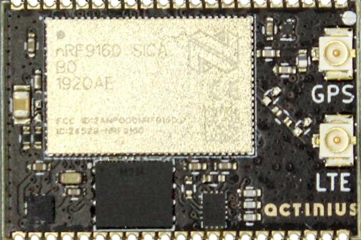
The Icarus SoM (System on Module) is a coin-sized, easy to solder solution that provides cutting edge low-power cellular IoT connectivity in module form. It is meant to be integrated into other electronics designs and can be powered using a 3.3 V regulator or directly through a LiPo battery. The module includes global LTE-M & NB-IoT connectivity, GPS, low-power 3-axis accelerometer, and a SIM switching circuit that allows the user to choose between the onboard eSIM or an externally connected SIM. All of this in a 18.5 x 28.0 mm package with castellated pins.
Features
- Application processor:
- ARM® Cortex M33 with 1 MB Flash and 256 kB RAM
- ARM® Trustzone®, ARM® Cryptocell 310
- Connectivity:
- LTE Cat-M1, LTE CAT-NB1 (NB-IoT) with Global Coverage
- SSL / TLS & Secure FOTA support
- PSM and eDRX support
- On-board eSIM & SIM switching circuit for external SIM
- GPS (L1 C/A)
- LIS2DH12 3-axis low-power accelerometer
- Power:
- GPIO and onboard peripherals powered through single 3.3 V pin
- VIN pin for powering directly from a battery or to separately power the radio.
- Peripherals:
- I2C / UART / SPI / I2S with EasyDMA
- up to 27 GPIO
- up to 8 12-bit, 200ksps ADC with EasyDMA
- up to 4 PWM Units
- SWD programming pins
- Fully integratable into other products due to castellated pins and SMD footprint
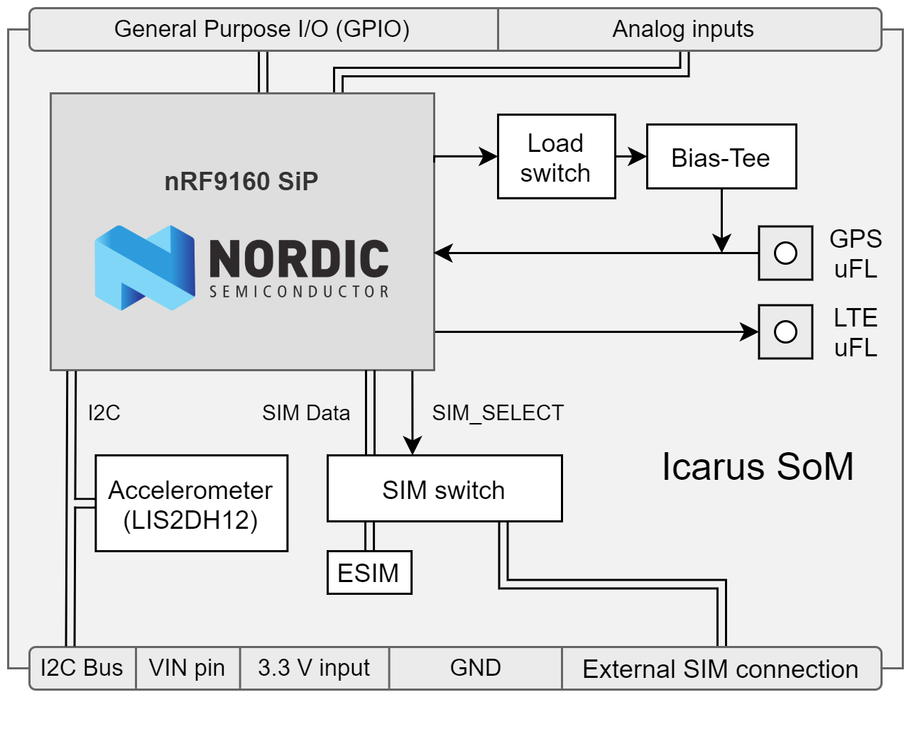
Block Diagram
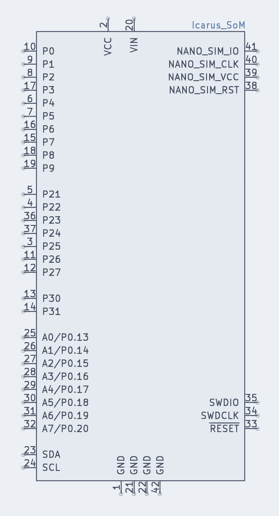
Pin description
External pins available to user
| # | Label | Description | Device-tree node |
|---|---|---|---|
| 1 | GND | Ground power input | - |
| 2 | VCC | Main power input | - |
| 3 | P25 | nRF9160 P0.25 | gpio0 |
| 4 | P22 | nRF9160 P0.22 | gpio0 |
| 5 | P21 | nRF9160 P0.21 | gpio0 |
| 6 | P4 | nRF9160 P0.04 | gpio0 |
| 7 | P5 | nRF9160 P0.05 | gpio0 |
| 8 | P2 | nRF9160 P0.02 | gpio0 |
| 9 | P1 | nRF9160 P0.01 | gpio0 |
| 10 | P0 | nRF9160 P0.00 | gpio0 |
| 11 | P26 | nRF9160 P0.26 | gpio0 |
| 12 | P27 | nRF9160 P0.27 | gpio0 |
| 13 | P30 | nRF9160 P0.30 | gpio0 |
| 14 | P31 | nRF9160 P0.31 | gpio0 |
| 15 | P7 | nRF9160 P0.07 | gpio0 |
| 16 | P6 | nRF9160 P0.06 | gpio0 |
| 17 | P3 | nRF9160 P0.03 | gpio0 |
| 18 | P8 | nRF9160 P0.08 | gpio0 |
| 19 | P9 | nRF9160 P0.09 | gpio0 |
| 20 | VIN | Direct battery / radio power input | - |
| 21 | GND | Ground power input | - |
| 22 | GND | Ground power input | - |
| 23 | SDA | I2C SDA pin | i2c2 |
| 24 | SCL | I2C SCL pin | i2c2 |
| 25 | A0 / P13 | AIN0 / nRF9160 P0.13 | gpio0 |
| 26 | A1 / P14 | AIN1 / nRF9160 P0.14 | gpio0 |
| 27 | A2 / P15 | AIN2 / nRF9160 P0.15 | gpio0 |
| 28 | A3 / P16 | AIN3 / nRF9160 P0.16 | gpio0 |
| 29 | A4 / P17 | AIN4 / nRF9160 P0.17 | gpio0 |
| 30 | A5 / P18 | AIN5 / nRF9160 P0.18 | gpio0 |
| 31 | A6 / P19 | AIN6 / nRF9160 P0.19 | gpio0 |
| 32 | A7 / P20 | AIN7 / nRF9160 P0.20 | gpio0 |
| 33 | RESET | nRF9160 Reset | - |
| 34 | SWDCLK | SWDCLK programming pin | - |
| 35 | SWDIO | SWDIO programming pin | - |
| 36 | P23 | nRF9160 P0.23 | gpio0 |
| 37 | P24 | nRF9160 P0.24 | gpio0 |
| 38 | NANO_SIM_RST | External SIM Reset | - |
| 39 | NANO_SIM_VCC | External SIM VCC | - |
| 40 | NANO_SIM_CLK | External SIM Clock | - |
| 41 | NANO_SIM_IO | External SIM IO | - |
| 42 | GND | Ground power input | - |
nRF9160 pins connected on Icarus SoM internally
| nRF9160 pin | Function | Device-tree node |
|---|---|---|
| P0.12 | SIM select pin | gpio0 |
| P0.28 | Accelerometer Interrupt 2 | lis2dh12-accel |
| P0.29 | Accelerometer Interrupt 1 | lis2dh12-accel |
The connections described in the table above connect the Accelerometer and SIM switching circuit with the nRF9160 on the Icarus SoM. They are not externally available to the user and are reserved for the specified functionality. These reserved nRF9160 pins should not be used for other functionalities. Using them can cause some devices on the Icarus SoM to stop working correctly.
Recommended Operating Conditions
| Parameter | MIN | TYP | MAX | UNITS |
|---|---|---|---|---|
| Operating Temperature | -20 | 25 | 85 | °C |
| VCC | 1.8 | 3.6 | V | |
| VIN | 3.0* | 3.8 | 5.5 | V |
(*) RF 3GPP compliance requires VIN >= 3.3 V
Dimensions
| Parameter | VALUE | UNITS |
|---|---|---|
| Height | 28 | mm |
| 1.1 | in. | |
| Width | 18.5 | mm |
| 0.73 | in. |
Peripherals
The Icarus SoM hosts several peripherals that are connected to the nRF9160 internally or on the board. Descriptions of the peripherals and devices can be found below.
Accelerometer
The accelerometer on the board is the LIS2DH12 from ST. This ultra-low-power 3-axis accelerometer is connected to the nRF9160 through I2C (address 0x19) and features two interrupt pins, INT1 and INT2, which are connected to pins P0.28 and P0.29. The interrupt pins can be configured for multiple purposes including free-fall and motion detection (more info on this in the LIS2DH12 datasheet).
The accelerometer hardware connection has been described in the Icarus device-tree under the i2c2 node. It has been defined as device lis2dh12-accel@19 with label LIS2DH12-ACCEL. For an example on how to read data from the accelerometer, see the Accelerometer sample.
GPS
The GPS receiver on the Icarus is embedded into the modem of the nRF9160. To successfully get a GPS fix, and receive location data, an active external GPS antenna must be connected (with a u.fl connector). An example of an antenna that can be used is the GNSS active patch antenna from Molex.
Configuring the voltage supply for the GPS antenna:
During operation, the modem inside the nRF9160 will automatically enable/disable the voltage supply for the GPS antenna when the GPS is active. It is doing this through the MAGPIO0 pin. During bootup, it is necessary to configure the modem through an AT command to use the MAGPIO pin. AT commands can be written to the nRF9160 modem using the at_cmd_write() function. This is an example of configuring the MAGPIO0 pin for GPS operation (notice how a specific frequency range for GPS is configured):
at_cmd_write("AT%XMAGPIO=1,0,0,1,1,1574,1577", NULL, 0, NULL);
Initialization and enabling of the GPS takes a few more steps. See the GPS sample in the nrf/samples folder and/or Nordic's nRF Connect SDK documentation for more information on initialization and reading GPS data using the Icarus.
eSIM and external SIM connection
SIM selection:
The Icarus SoM provides the user with 2 options regarding SIM usage for LTE-M/NB-IoT communication. Either using the on-board eSIM or using an external nano-SIM. The SIM can be selected using the SIM select pin on P0.12:
| Selection pin (P0.08) | Selected SIM |
|---|---|
| HIGH (1) | on-board eSIM |
| LOW (0) | external nano-SIM |
If the pin is left uninitialized, the modem will use the on-board eSIM.
Only change the SIM Select pin before enabling the modem. E.g. before writing the "AT+CFUN=1" AT command.
SIM select configuration for nRF SDK v2.0.0 and up: The SIM on the Icarus SoM must be selected through the device-tree if you are using nRF SDK v2.0.0 and up. Selecting the SIM is done using a device-tree overlay file in your project. Follow these steps to select the SIM through the device-tree:
- Create a new directory in your project folder named
boards:
$ cd <your-project-directory>
$ mkdir boards
$ cd boards
- Create an overlay file with the exact name of the board:
# When building for a non-secure application
$ touch actinius_icarus_som_ns.overlay
- Add the following device-tree node to your overlay file:
&sim_select {
    sim = "external";
};
By changing the value of sim to "external" you select the external SIM. By changing the value of sim to "esim" you select the on-board eSIM. And what's left to do is to re-build your project (use a pristine build).
SIM select configuration for nRF SDK v1.9.1 and down:
The external SIM on the Icarus SoM can be selected using a configuration option if you are using nRF SDK v1.9.1 and down. You can set the following option: BOARD_SELECT_SIM_EXTERNAL=y in the prj.conf to automatically select the external SIM on the SIM connector. The on-board eSIM is used by default if the config option is not set.
Power
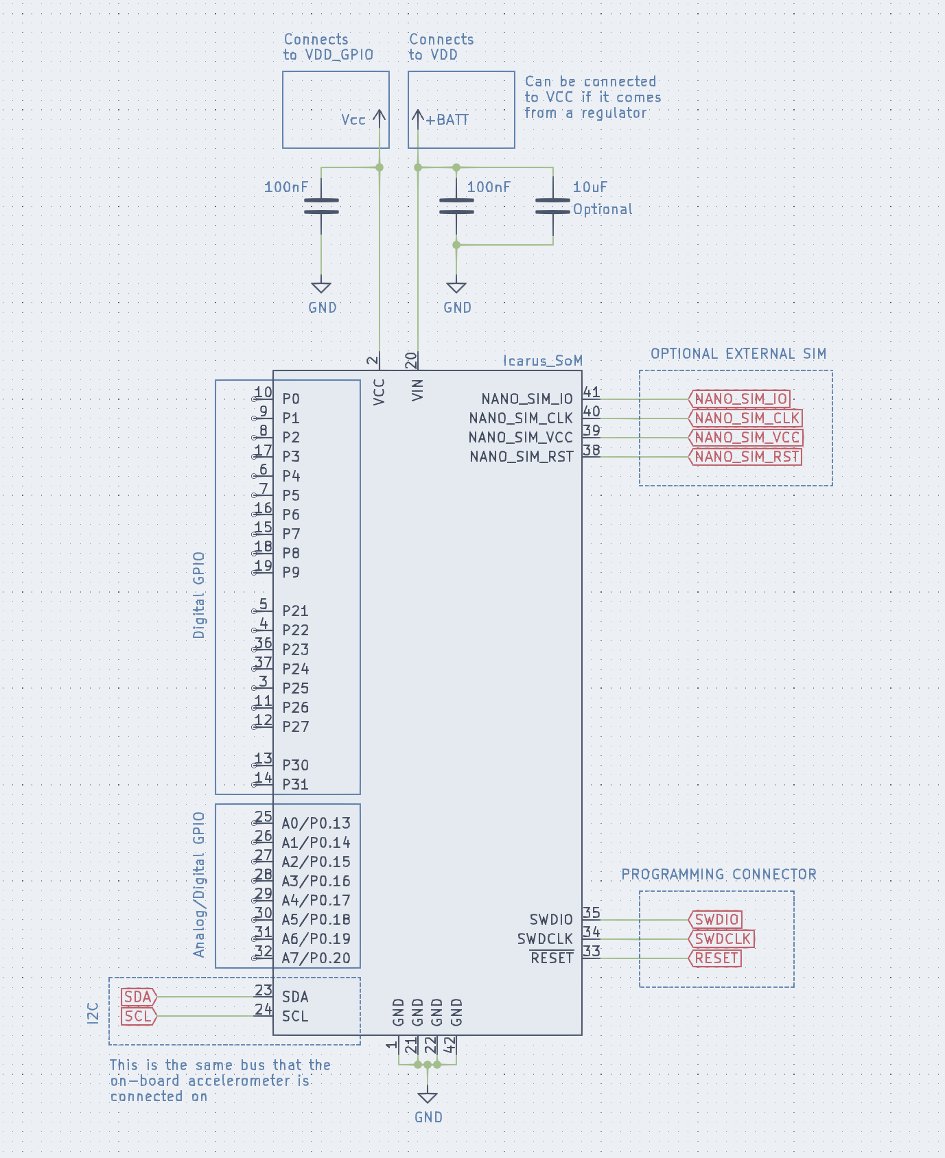
VIN can be powered by LiPo battery directly. VCC should be powered by a small regulator (depends mostly on usage of GPIOs).
Icarus SoM reference design (application circuit)
CAD Symbols and Footprints
Symbols and footprints for the Icarus SoM are available for all popular CAD software on SnapEDA