Icarus SoM DK v2 Datasheet
Overview
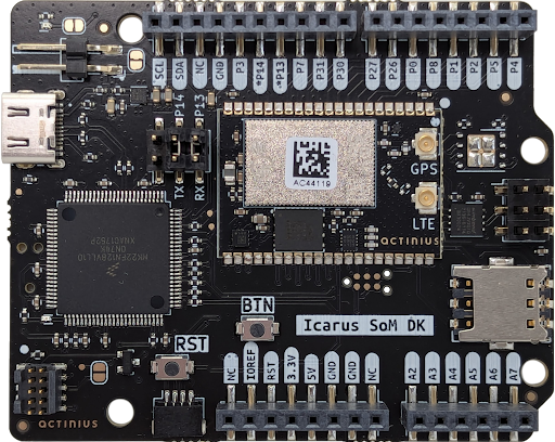
The Icarus SoM DK v2 is a single board development kit for evaluation and development on the Icarus SoM. The Icarus SoM features the nRF9160 SiP from Nordic Semiconductor which provides low-power LTE-M and NB-IoT connectivity, GPS, a low-power 3-axis accelerometer and an on-board eSIM. The development kit provides interfacing to the SoM through USB-C, an LED, reset and user buttons, battery charging, power management, an external nano SIM connector. Also, new to the v2: an on-board J-Link programmer and a STEMMA-QT connector. The board is also Arduino Uno Rev3 compatible which makes using external shields possible.
Features
- Icarus System on Module
- Application processor:
- ARM® Cortex M33 with 1 MB Flash and 256 kB RAM
- ARM® Trustzone®, ARM® Cryptocell 310
- Connectivity:
- LTE Cat-M1, LTE CAT-NB1 (NB-IoT) with Global Coverage
- SSL / TLS & Secure FOTA support
- PSM and eDRX support
- On-board eSIM & SIM switching circuit for external SIM
- GPS (L1 C/A)
- Sensors, devices, and buttons:
- LIS2DH12 3-axis low-power accelerometer
- 64 Mbit SPI NOR flash
- User LED
- General Purpose button
- Reset button
- Power:
- USB-C connector
- 5V pin for powering directly from a battery or otherwise
- Current measurement connector
- Peripherals:
- On-board Segger J-Link programmer
- I2C / UART / SPI / I2S with EasyDMA
- up to 20 GPIO
- up to 8 12-bit, 200ksps ADC with EasyDMA
- up to 4 PWM Units
- SWD 10-pin JTAG programming connector
- SWD 6-pin TagConnect programming connector
- StemmaQT connector for additional external GPIO
- Compatible with the Arduino Uno Rev3
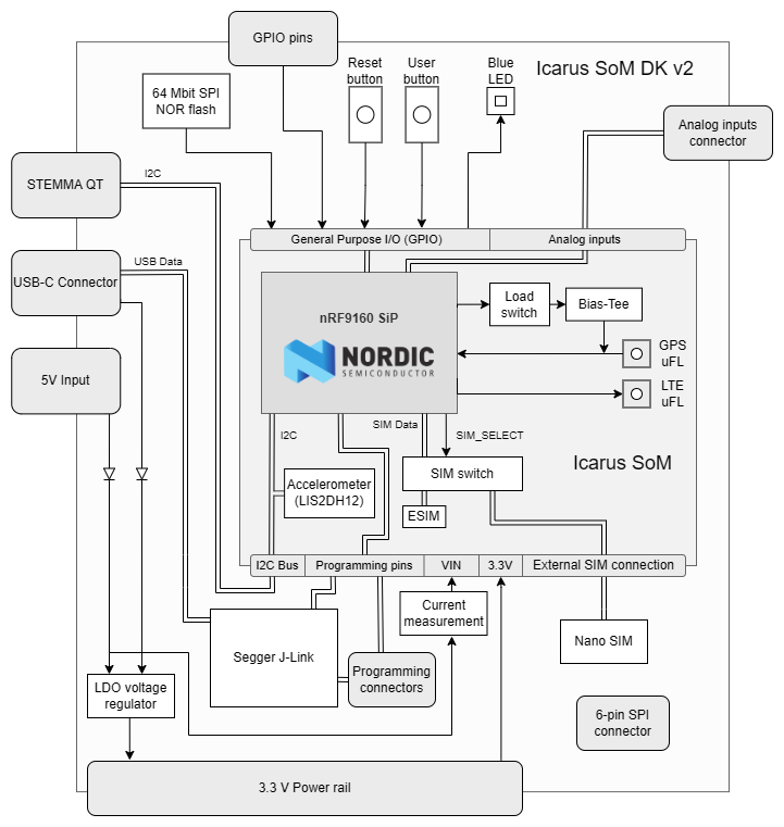
Block Diagram
Pin description
External pins available to user
| # | Label | Description | Device-tree node |
|---|---|---|---|
| 1 | NC | Not Connected | - |
| 2 | IOREF | I/O reference, connected to 3.3V | - |
| 3 | RST | Reset of the nRF9160 | - |
| 4 | 3.3V | 3.3V Power output | - |
| 5 | 5V | Power input pin | - |
| 6 | GND | Ground pin | - |
| 7 | GND | Ground pin | - |
| 8 | NC | Not Connected | - |
| 9 | A2 | AIN2 / nRF9160 P0.15 | gpio0 |
| 10 | A3 | AIN3 / nRF9160 P0.16 | gpio0 |
| 11 | A4 | AIN4 / nRF9160 P0.17 | gpio0 |
| 12 | A5 | AIN5 / nRF9160 P0.18 | gpio0 |
| 13 | A6 | AIN6 / nRF9160 P0.19 | gpio0 |
| 14 | A7 | AIN7 / nRF9160 P0.20 | gpio0 |
| 15 | P4 | nRF9160 P0.04 | gpio0 |
| 16 | P5 | nRF9160 P0.05 | gpio0 |
| 17 | P2 | nRF9160 P0.02 | gpio0 |
| 18 | P1 | nRF9160 P0.01 | gpio0 |
| 19 | P8 | nRF9160 P0.08 | gpio0 |
| 20 | P0 | nRF9160 P0.00 | gpio0 |
| 21 | P26 | nRF9160 P0.26 | gpio0 |
| 22 | P27 | nRF9160 P0.27 | gpio0 |
| 23 | P30 | nRF9160 P0.30 | gpio0 |
| 24 | P31 | nRF9160 P0.31 | gpio0 |
| 25 | P7 | nRF9160 P0.07 | gpio0 |
| 26 | P13 | AIN0 / nRF9160 P0.13 | gpio0 |
| 27 | P14 | AIN1 / nRF9160 P0.14 | gpio0 |
| 28 | P3 | nRF9160 P0.03 | gpio0 |
| 29 | GND | Ground pin | - |
| 30 | NC | Not Connected | - |
| 31 | SDA | I2C SDA pin | i2c2 |
| 32 | SCL | I2C SCL pin | i2c2 |
nRF9160 pins connected on the Icarus SoM DK v2 internally
| nRF9160 pin | Function | Device-tree node |
|---|---|---|
| P0.03 | Blue LED | led0 / pwm-led0 |
| P0.12 | SIM select pin | gpio0 |
| P0.23 | Connected to the user button | gpio0 / button0 |
| P0.24 | SPI NOR Flash chip select | gpio0 / spi3 |
| P0.28 | Accelerometer Interrupt 2 | lis2dh12-accel |
| P0.29 | Accelerometer Interrupt 1 | lis2dh12-accel |
The connections described in the table above are reserved for the specified functionality and should not be used for other functionalities. Using them can cause some devices on the Icarus SoM DK v2 to stop working correctly.
Recommended Operating Conditions
| Parameter | MIN | TYP | MAX | UNITS |
|---|---|---|---|---|
| Operating Temperature | -20 | 25 | 85 | °C |
| V_USB Voltage | 4.35 | 5 | 5.5 | V |
| 5V Pin Voltage | 4.35 | 5 | 5.5 | V |
| 3.3V Pin Voltage | 3.3 | 3.3 | 3.3 | V |
Dimensions
| Parameter | VALUE | UNITS |
|---|---|---|
| Height | 55.2 | mm |
| 2.17 | in. | |
| Width | 68.57 | mm |
| 2.7 | in. |
Programming
Programming over USB
The Icarus SoM DK v2 now features an on-board Segger J-Link programmer, allowing for the Icarus SoM to be flashed directly from a PC through USB-C, without needing MCUBoot or an external J-Link programmer.
The on-board programmer also means that the DK v2 is detected by the nRF Connect VSCode extension as a programmable device, meaning development and flashing can be done in the same environment. For more information about using VSCode to flash applications, please refer to: Flashing an application using J-Link and TagConnect.
Programming other boards
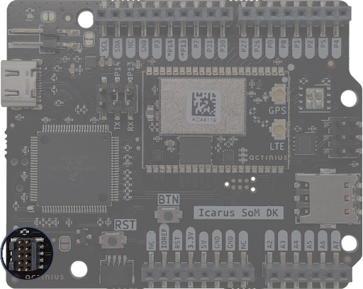
The v2 DK also includes a 10-pin 50mil FTSH style header, allowing it to be used to program other development boards. When another board is connected to the programming header and is powered on, the DK can detect it, and will flash applications to the other board rather than the Icarus SoM.
Programming with TagConnect pins
As a back-up, it is also still possible to flash applications to the Icarus SoM using the 6-pin TagConnect programming pins. However, this of course requires another board containing a J-Link programmer.
Peripherals
The Icarus SoM DK v2 hosts several peripherals that are connected to the nRF9160 internally or on the board. Descriptions of the peripherals and devices can be found below.
Segger J-Link on-board chip
In addition to making flashing applications easier, the J-Link chip also provides serial communication over the USB-C port using UART. In total 3 UART connections are possible, however the Icarus SoM DK v2 only implements 2 of them. When connecting the Icarus SoM DK v2 to a PC, 3 new communication ports will become available. By default, UART communication with the Icarus SoM is available on the first port and can be read using an appropriate program like Tera Term or PuTTY. Since MCUBoot is no longer needed to program over the USB port, this UART connection can be kept alive whilst flashing applications too.
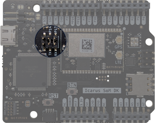
A second UART connection is also available for modem tracing, but it must be configured first. There is a 6 pin jumper on the Icarus SoM DK v2 which is used to connect pins 13 and 14 of the nRF9160 to RX and TX pins on the J-Link chip. This connection must be made in order for UART data to be available on the USB-C port, which is done by default using 2-pin jumper plugs.
In order to enable modem tracing in your application some additions also need to be made to the devicetree and KConfig. More information on this can be found on Nordic's website
STEMMA QT connector
The Icarus SoM DK v2 board provides a STEMMA QT connector, which is a small 4-pin JST SH connector. This allows for further external sensors or other devices to be connected to the Icarus SoM over I2C.
SPI NOR Flash
The Icarus SoM DK v2 board provides the W25Q64JV with 64 MBit of SPI NOR flash, supported by Zephyr. This allows for storage of larger amounts of data. It also allows to store firmware update images on the flash which are received Over-The-Air (OTA).
The SPI NOR flash hardware connection has been described in the Icarus SoM DK v2 device-tree under the arduino_spi / spi3 node. It has been defined as device w25q64jv@0 with label W25Q64. The flash can be selected using its Chip Select (CS) which is connected on P0.24 of the nRF9160. The SPI NOR flash can be tested using the JEDEC SPI-NOR Sample from Zephyr.
Accelerometer
The accelerometer on the board is the LIS2DH12 from ST. This ultra-low-power 3-axis accelerometer is connected to the nRF9160 through I2C (address 0x19) and features two interrupt pins, INT1 and INT2, which are connected to pins P0.28 and P0.29. The interrupt pins can be configured for multiple purposes including free-fall and motion detection (more info on this in the LIS2DH12 datasheet).
The accelerometer hardware connection has been described in the Icarus SoM DK v2 device-tree under the arduino_i2c / i2c2 node. It has been defined as device lis2dh12-accel@19 with label LIS2DH12-ACCEL. For an example on how to read data from the accelerometer, see the Accelerometer sample.
GPS
The GPS receiver on the Icarus SoM DK v2 is embedded into the modem of the nRF9160. To successfully get a GPS fix, and receive location data, an active external GPS antenna must be connected (with a u.fl connector). An example of an antenna that can be used is the GNSS active patch antenna from Molex.
Configuring the voltage supply for the GPS antenna:
During operation, the modem inside the nRF9160 will automatically enable/disable the voltage supply for the GPS antenna when the GPS is active. It is doing this through the MAGPIO0 pin. During bootup, it is necessary to configure the modem through an AT command to use the MAGPIO pin. AT commands can be written to the nRF9160 modem using the at_cmd_write() function. This is an example of configuring the MAGPIO0 pin for GPS operation (notice how a specific frequency range for GPS is configured):
at_cmd_write("AT%XMAGPIO=1,0,0,1,1,1547,1577", NULL, 0, NULL);
Initialization and enabling of the GPS takes a few more steps. See the GPS sample in the nrf/samples folder and/or Nordic's nRF Connect SDK documentation for more information on initialization and reading GPS data using the Icarus.
eSIM and external SIM connection
The SIM must be selected through the device-tree if you are using nRF SDK v2.0.0 and up. Selecting the SIM is done using a device-tree overlay file in your project. Follow these steps to select the SIM through the device-tree:
- Create a new directory in your project folder named
boards:
$ cd <your-project-directory>
$ mkdir boards
$ cd boards
- Create an overlay file with the exact name of the board:
# When building for a non-secure application
$ touch actinius_icarus_som_dk_ns.overlay
- Add the following device-tree node to your overlay file:
&sim_select {
    sim = "external";
};
By changing the value of sim to "external" you select the external SIM. By changing the value of sim to "esim" you select the on-board eSIM. And what's left to do is to re-build your project (use a pristine build).
If the pin is left uninitialized, the modem will use the on-board eSIM.
Only change the SIM Select pin before enabling the modem. E.g. before writing the "AT+CFUN=1" AT command.
Power
The board can be powered using USB-C or the 5V pin, which both provide the 5V input needed to power the nRF9160 on the Icarus SoM. An LDO (Low Drop-Out) voltage regulator on the DK then provides a stable 3.3V voltage rail from the 5V input, which is used to power the various peripherals on the board.
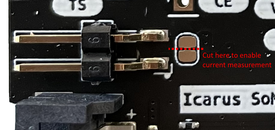
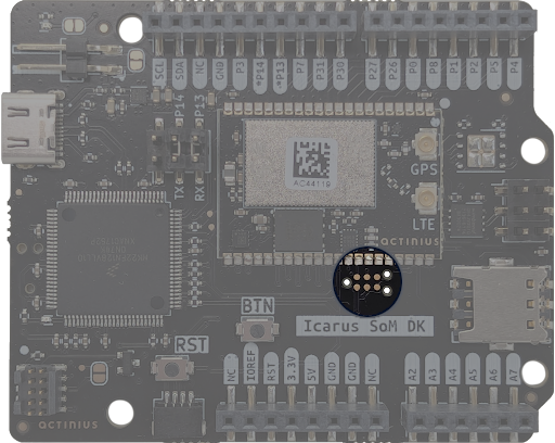
SoM current consumption measurement
The DK provides a way to measure the current consumption of the Icarus SoM by using the 2-pin header next to the battery connector. The pins can be connected to a multimeter or e.g. an OTII measurement device. The use of the 2-pin header to measure current requires you to cut the jumper next to it. When done measuring the current consumption, this jumper should be resoldered to ensure that the SoM gets powered.