Icarus Bee Datasheet
Overview
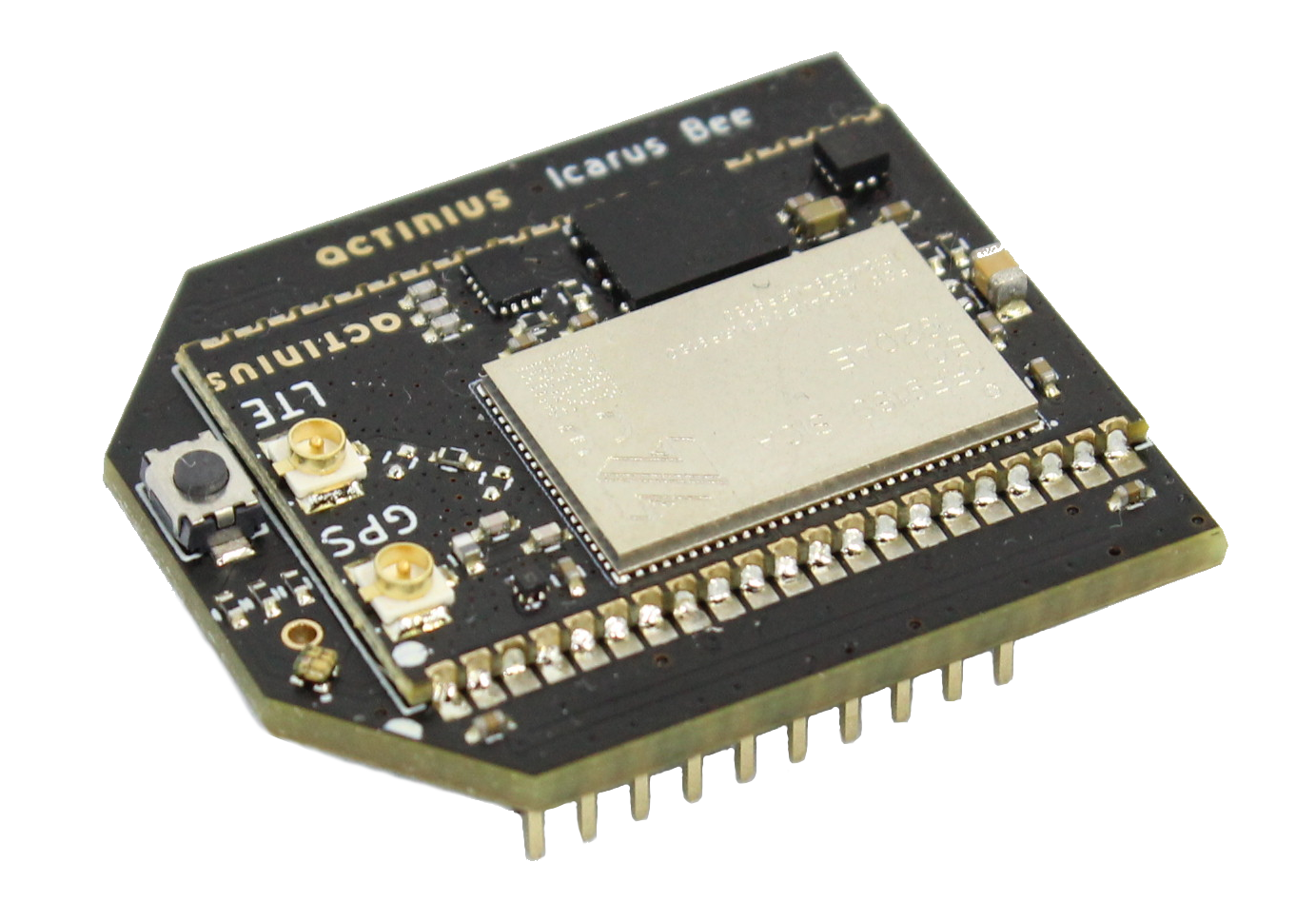
The Icarus Bee is a small XBee module based on the Icarus SoM (System on Module). It can be used to replace your legacy LoRa, Zigbee or 2G/3G Bee module with cutting edge Low Power Cellular IoT connectivity. The Icarus Bee hosts a nRF9160 SiP which contains an ARM® Cortex M33 processor used for user applications. The SiP also contains a second processor that is dedicated to cellular communication (LTE-M / NB-IoT) and GPS.
The nRF9160 modem supports Power Saving Mode (PSM) to extend battery life and minimize power consumption. In PSM mode the Icarus sets a sleep timer, tells the network it will not be reachable during sleep. It will not be able to communicate until it wakes up again, but it can wake up at any time if it wants to connect and send data. The modem also supports extended discontinuous reception (eDRX). This allows the user to configure predefined intervals on which the board should wake up to listen for network messages. PSM and/or eDRX can be used together to prolong battery life and minimize power consumption.1
User applications are usually run on Zephyr RTOS. This is a scalable real-time operating system (RTOS) for embedded devices that have constrained resources. The OS borrows elements from Linux and may be familiar to Linux developers: e.g. kernel configuration using Kconfig and usage of the device-tree. Nordic Semiconductor has created its own fork of Zephyr which can be found here.
Features
- Application processor:
- ARM® Cortex M33 with 1 MB Flash and 256 kB RAM
- ARM® Trustzone®, ARM® Cryptocell 310
- Connectivity:
- LTE Cat-M1, LTE CAT-NB1 (NB-IoT) with Global Coverage
- SSL / TLS & Secure FOTA support
- PSM and eDRX support
- On-board eSIM & nano SIM
- GPS (L1 C/A)
- Sensors, devices, and buttons:
- LIS2DH12 3-axis low-power accelerometer
- 64 Mbit SPI NOR Flash
- RGB LED
- General Purpose button
- Power:
- Powered through a single 3.3 V supply pin
- Peripherals:
- USB / I2C / UART / SPI / I2S with EasyDMA
- up to 13 GPIO
- up to 6 12-bit, 200ksps ADC with EasyDMA
- up to 4 PWM Units
- SWD programming pins accessible through the pin connectors
- Fully compatible with the XBee form factor
Pin description
External Pins available to user
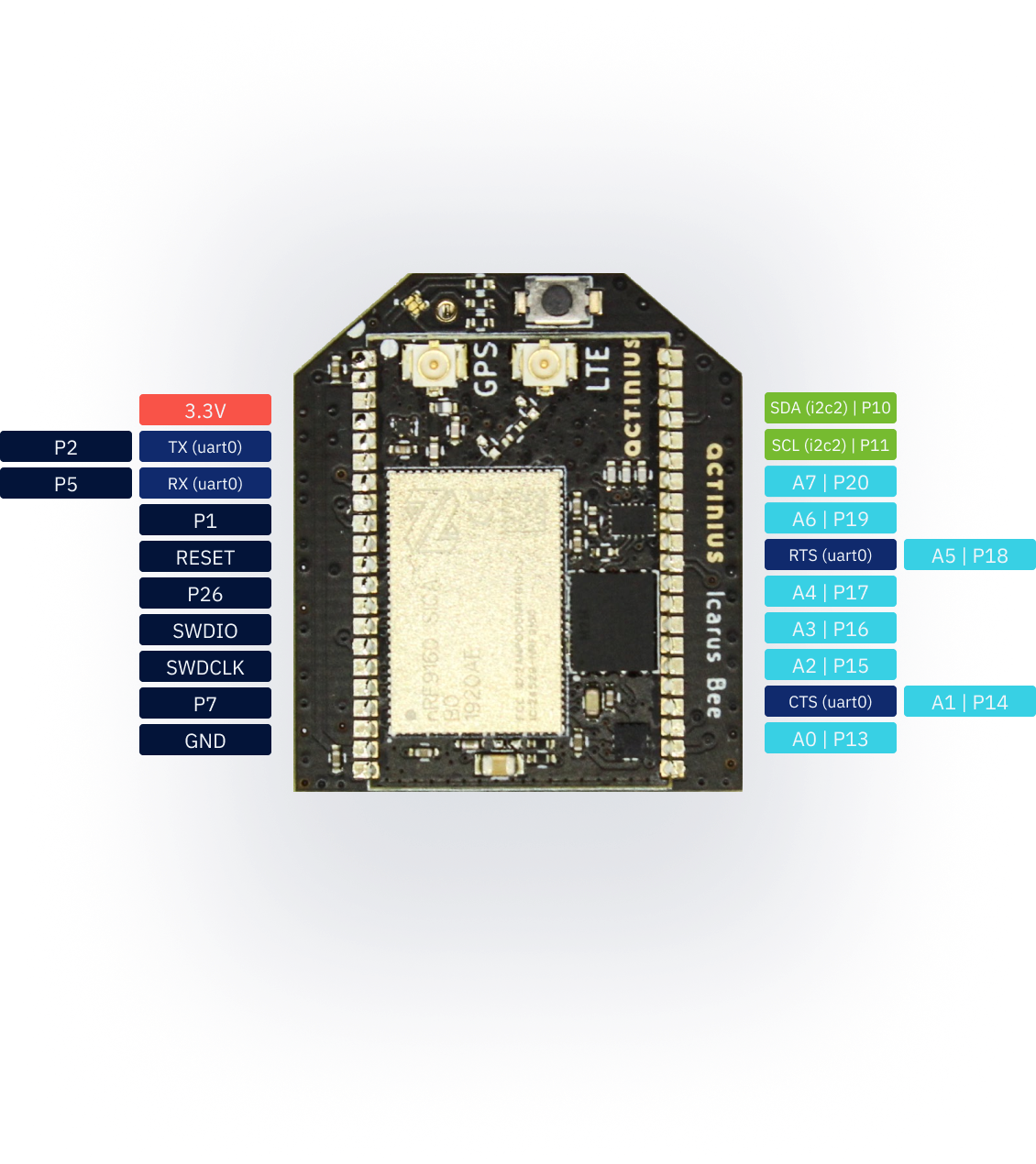
| Icarus pin | Function | Description | Device-tree node |
|---|---|---|---|
| 3.3V | Power input | Main 3.3 V supply | - |
| P2 / TX | GPIO / UART pin | nRF9160 P0.02 / UART TX pin | gpio0 / uart0 |
| P5 / RX | GPIO / UART pin | nRF9160 P0.05 / UART RX pin | gpio0 / uart0 |
| P1 | GPIO | nRF9160 P0.01 | gpio0 |
| RESET | Reset | Active low reset with internal pullup | - |
| P26 | GPIO | nRF9160 P0.26 | gpio0 |
| SWDIO | SWD programming pin | SWDIO pin for programming | - |
| SWDCLK | SWD programming pin | SWDCLK pin for programming | - |
| P7 | GPIO | nRF9160 P0.07 | gpio0 |
| GND | Power input | Ground | - |
| SDA | GPIO / I2C pin | nRF9160 P0.10 / I2C SDA pin | gpio0 / i2c2 |
| SCL | GPIO / I2C pin | nRF9160 P0.11 / I2C SCL pin | gpio0 / i2c2 |
| P20 / A7 | GPIO / Analog in | nRF9160 P0.20 / AIN7 | gpio0 / adc_7 |
| P19 / A6 | GPIO / Analog in | nRF9160 P0.19 / AIN6 | gpio0 / adc_6 |
| RTS / P18 / A5 | UART pin / GPIO / Analog in | UART RTS pin / nRF9160 P0.18 / AIN5 | uart0 / gpio0 / adc_5 |
| P17 / A4 | GPIO / Analog in | nRF9160 P0.17 / AIN4 | gpio0 / adc_4 |
| P16 / A3 | GPIO / Analog in | nRF9160 P0.16 / AIN3 | gpio0 / adc_3 |
| P15 / A2 | GPIO / Analog in | nRF9160 P0.15 / AIN2 | gpio0 / adc_2 |
| CTS / P14 / A1 | UART pin / GPIO / Analog in | nRF9160 P0.14 / nRF9160 P0.14 / AIN1 | uart0 / gpio0 / adc_1 |
| P13 / A0 | GPIO / Analog in | nRF9160 P0.13 / AIN0 | gpio0 / adc_0 |
nRF9160 pins connected on Icarus Bee internally
| nRF9160 pin | Function | Device-tree node |
|---|---|---|
| P0.04 | User button | button0 |
| P0.21 | Red LED | led0 / pwm-led0 |
| P0.22 | Green LED | led1 / pwm-led1 |
| P0.25 | Blue LED | led2 / pwm-led2 |
| P0.29 | Accelerometer Interrupt 1 | lis2dh12-accel |
| P0.28 | Accelerometer Interrupt 2 | lis2dh12-accel |
| P0.12 | SIM select pin | gpio0 |
| P0.03 | MOSI pin for SPI | spi3 |
| P0.08 | MISO pin for SPI | spi3 |
| P0.06 | SCK pin for SPI | spi3 |
| P0.09 | FLASH memory SPI CS pin | gpio0 |
The connections described in the table above connect several devices with the nRF9160 on the Icarus Bee. They are not externally available to the user and are reserved for the specified functionality. These reserved nRF9160 pins should not be used for other functionalities. Using them can cause some devices on the Icarus Bee to stop working correctly.
Recommended Operating Conditions
| Parameter | MIN | TYP | MAX | UNITS |
|---|---|---|---|---|
| Operating Temperature | -20 | 25 | 85 | °C |
| Input Voltage | 3.0 | 3.3 | 3.6 | V |
Dimensions
| Parameter | VALUE | UNITS |
|---|---|---|
| Height | 32.53 | mm |
| 1.28 | in. | |
| Width | 27.84 | mm |
| 1.10 | in. |
Devices
The Icarus Bee hosts several devices that are connected to the nRF9160 through internal connections. The pins used for the connections are reserved and should not be used for other purposes (as already described in the Icarus Bee pin description).
SPI NOR Flash
The Icarus Bee contains the W25Q64JV 64 MBit SPI NOR flash which is supported by Zephyr. This allows for storage of larger amounts of data. It also allows to store firmware update images on the flash which are received Over-The-Air (OTA).
The SPI NOR flash hardware connection has been described in the Icarus Bee device-tree under the spi3 node. It has been defined as device w25q64jv@0 with label W25Q64. The SPI NOR flash can be tested using the JEDEC SPI-NOR Sample from Zephyr.
Accelerometer
The accelerometer on the board is the LIS2DH12 from ST. This ultra-low-power 3-axis accelerometer is connected to the nRF9160 through I2C (address 0x19) and features two interrupt pins, INT1 and INT2, which are connected to pins P0.29 and P0.28. The interrupt pins can be configured for multiple purposes including free-fall and motion detection (more info on this in the LIS2DH12 datasheet).
The accelerometer hardware connection has been described in the Icarus Bee device-tree under the i2c2 node. It has been defined as device lis2dh12-accel@19 with label LIS2DH12-ACCEL. For an example on how to read data from the accelerometer, see the Accelerometer sample.
GPS
The GPS receiver on the Icarus is embedded into the modem of the nRF9160. To successfully get a GPS fix, and receive location data, an active external GPS antenna must be connected (with a u.fl connector). An example of an antenna that can be used is the GNSS active patch antenna from Molex.
Configuring the voltage supply for the GPS antenna:
During operation, the modem inside the nRF9160 will automatically enable/disable the voltage supply for the GPS antenna when the GPS is active. It is doing this through the MAGPIO0 pin. During bootup, it is necessary to configure the modem through an AT command to use the MAGPIO pin. AT commands can be written to the nRF9160 modem using the at_cmd_write() function. This is an example of configuring the MAGPIO0 pin for GPS operation (notice how a specific frequency range for GPS is configured):
at_cmd_write("AT%XMAGPIO=1,0,0,1,1,1574,1577", NULL, 0, NULL);
Initialization and enabling of the GPS takes a few more steps. See the GPS sample in the nrf/samples folder and/or Nordic's nRF Connect SDK documentation for more information on initialization and reading GPS data using the Icarus.
eSIM and external SIM
SIM selection:
The Icarus Bee provides the user with 2 options regarding SIM usage for LTE-M/NB-IoT communication. Either using the on-board eSIM or using an external nano-SIM. The SIM can be selected using the SIM select pin on P0.08:
| Selection pin (P0.08) | Selected SIM |
|---|---|
| HIGH (1) | on-board eSIM |
| LOW (0) | external nano-SIM |
If the pin is left uninitialized, the modem will use the on-board eSIM.
Only change the SIM Select pin before enabling the modem. E.g. before writing the "AT+CFUN=1" AT command.
SIM select configuration for nRF SDK v2.0.0 and up: The SIM on the Icarus Bee must be selected through the device-tree if you are using nRF SDK v2.0.0 and up. Selecting the SIM is done using a device-tree overlay file in your project. Follow these steps to select the SIM through the device-tree:
- Create a new directory in your project folder named
boards:
$ cd <your-project-directory>
$ mkdir boards
$ cd boards
- Create an overlay file with the exact name of the board:
# When building for a non-secure application
$ touch actinius_icarus_bee_ns.overlay
- Add the following device-tree node to your overlay file:
&sim_select {
    sim = "external";
};
By changing the value of sim to "external" you select the external SIM. By changing the value of sim to "esim" you select the on-board eSIM. And what's left to do is to re-build your project (use a pristine build).
SIM select configuration for nRF SDK v1.9.1 and down:
The external SIM on the Icarus Bee can be selected using a configuration option if you are using nRF SDK v1.9.1 and down. You can set the following option: BOARD_SELECT_SIM_EXTERNAL=y in the prj.conf to automatically select the external SIM on the SIM connector. The on-board eSIM is used by default if the config option is not set.
Included eSIM dataplan: The on-board eSIM of the Icarus Bee provides LTE-M (and in the future NB-IoT) data connectivity, wherever supported by our Telecom Agreements in the EU and US. The Icarus Bee includes a free eSIM bundle with 10 MB of data for 3 months. A data plan can be purchased for the eSIM after the initial three months. The eSIM can be activated by registering your Icarus Bee on the Actinius IO platform.
Power
A single 3.3v supply is needed, which should be able to supply a peak current of about 400mA.
CAD Symbols and Footprints
Symbols and footprints for the Icarus Bee are available for all popular CAD software on SnapEDA